CNC Machining Tolerances Explained: How to Specify Them for Oil & Gas Components
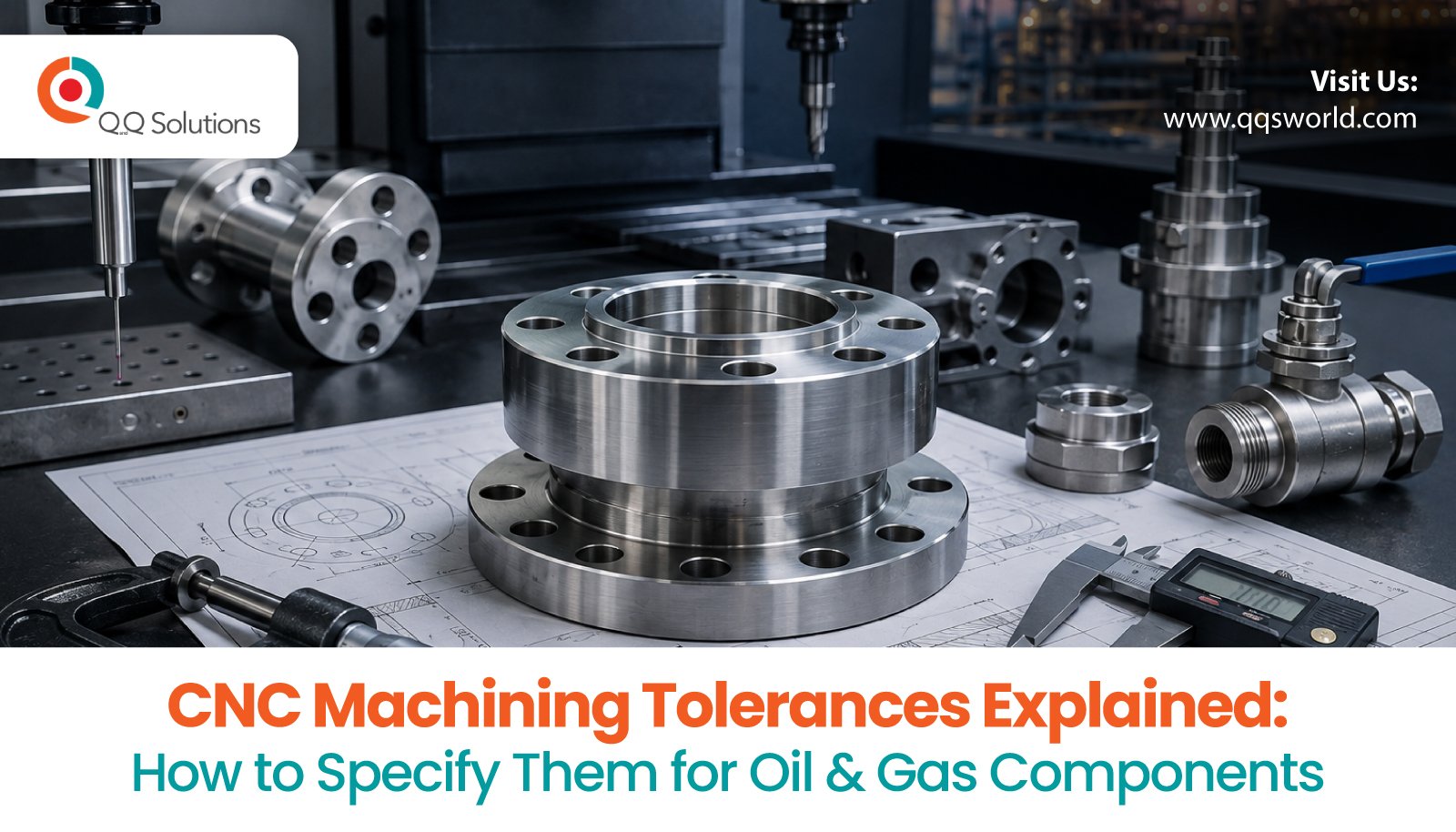
If you design or procure components for oil and gas applications, you already know that a tolerance callout on a drawing is never “just a number.” A 0.01 mm difference on a valve stem bore, a pump housing bore, or a flange face can be the difference between a component that seals for twenty years and one that fails a hydro test on day one. Yet tolerance specification is one of the most inconsistently handled parts of the RFQ process — drawings arrive over-toleranced out of habit, under-toleranced out of oversight, or toleranced in a way that doesn’t match how the part will actually be inspected.
This guide breaks down how CNC machining tolerances work, how to specify them correctly for oil & gas components, and why the tolerance strategy you choose has a direct impact on cost, lead time, and long-term reliability in the field.
Why Tolerance Specification Matters More in Oil & Gas
Oil & gas components live in one of the least forgiving service environments in industrial manufacturing: high pressure, corrosive media, cyclic thermal loading, and — critically — very limited access for inspection or repair once installed. A wellhead valve body, a pump housing, or a manifold block isn’t something you can easily pull and re-machine six months into service.
That makes the tolerance stack on a component about more than fit and finish. It governs:
- Sealing performance — bore roundness and surface finish on sealing diameters directly affect gasket and O-ring life.
- Rotating equipment reliability — shaft-to-bore clearances on pump and turbine components determine vibration behavior and bearing life.
- Assembly interchangeability — for API-spec components built in batches, tight positional tolerances on bolt patterns and flange faces are what allow field replacement without on-site fitting.
- Pressure integrity — wall thickness tolerances on cast-and-machined pressure-containing parts feed directly into the pressure rating calculations.
Because of this, tolerance decisions in oil & gas machining are rarely made in isolation. They’re tied to the applicable code — API 6A, API 610, ASME B16.34, or a client-specific engineering standard — and to how the part will be verified: CMM, hard gauging, or manual inspection.
The Building Blocks: ISO 2768 vs. Tighter Custom Tolerances
Most CNC shops default to ISO 2768 general tolerances (classes f, m, c, v) for dimensions that aren’t functionally critical. This is appropriate and cost-effective for non-mating features — mounting bosses, non-sealing external profiles, general stock removal surfaces.
But general tolerances should never be relied on for functional features. For oil & gas work, the features that typically require explicit, tighter tolerance callouts are:
- Bore diameters for seals, bearings, and shafts — commonly IT6–IT8 grade tolerances (roughly ±0.01–0.03 mm depending on nominal size), not general ISO 2768 bands.
- Flange face flatness and perpendicularity — usually called out as a GD&T flatness or perpendicularity value relative to the bore axis, not a linear tolerance.
- Bolt circle positional tolerance — specified as true position with a diameter symbol, not as ± coordinates, so it accounts for the full circular tolerance zone rather than a square one.
- Wall thickness on cast-and-machined bodies — often controlled as a minimum stock allowance rather than a symmetric tolerance, since undersize walls are the failure mode that matters.
A useful rule of thumb: if a dimension affects sealing, rotation, or load transfer, it should have its own explicit tolerance and, ideally, a GD&T callout rather than a plus/minus dimension.
GD&T: Moving Beyond Plus/Minus Dimensioning
Geometric Dimensioning and Tolerancing (GD&T) exists precisely because plus/minus tolerancing breaks down on complex geometry. A flange bolt pattern toleranced with ± coordinates on each hole creates a square tolerance zone that’s actually more restrictive — and more expensive to hold — than the circular zone a true-position callout allows, for the same functional result.
For oil & gas components, the GD&T callouts that matter most are:
- True position — for bolt patterns and port locations, ensuring mating parts assemble without forcing.
- Flatness — for flange faces and gasket surfaces, since a flat face is what actually creates the seal, not just the diameter.
- Perpendicularity and concentricity — for bores relative to a datum axis, critical on valve bodies and pump housings where misalignment causes uneven wear.
- Runout — for rotating components like shafts and turbine hubs, where excess runout translates directly into vibration.
Specifying these correctly requires establishing a clear datum reference frame on the drawing — usually a primary datum on the largest flat face, a secondary datum on a locating bore, and a tertiary datum to lock rotation. Every other tolerance on the part should reference back to that frame, which is also how the part will actually be fixtured on the CNC machine and measured on the CMM. When the datum structure on the drawing matches the datum structure used in machining and inspection, tolerance stack-up disputes largely disappear.
Surface Finish: The Tolerance Nobody Talks About Enough
Dimensional tolerance gets most of the attention, but surface finish (Ra value) is just as consequential for oil & gas parts, particularly sealing and rotating surfaces:
- Static sealing faces (flange faces, gasket seats): typically Ra 3.2 µm or better, sometimes with a specified finish pattern.
- Dynamic sealing surfaces (valve stems, shaft journals): often Ra 0.4–0.8 µm to protect elastomer or mechanical seal life.
- Bearing bores: Ra 0.8–1.6 µm depending on bearing type and speed.
Over-specifying finish where it isn’t functionally needed is one of the most common (and avoidable) cost drivers in machining quotes. A blanket Ra 0.8 callout across an entire component, when only two surfaces actually need it, can add unnecessary grinding or polishing operations to every other feature on the part.
How Tolerance Choices Affect Cost and Lead Time
Every tolerance grade tighter than ISO 2768-m typically requires:
- Slower cutting parameters to control thermal expansion and tool deflection
- Additional in-process inspection (CMM checks between operations, not just final inspection)
- In some cases, a finishing pass or grinding operation after the primary CNC cycle
- Tighter fixture design and, for high-volume work, dedicated gauging
None of this means tight tolerances should be avoided — for functional features they’re non-negotiable — but it does mean tolerance specification should be deliberate. A drawing with every dimension held to ±0.02 mm “to be safe” doesn’t make the part more reliable; it makes it more expensive and slower to deliver, without improving the features that actually determine service life.
The most cost-efficient approach we see working with oil & gas OEMs and EPCs is a tiered tolerance strategy: general ISO 2768-m or c tolerances as the baseline, tight IT6–IT8 and GD&T callouts only on features tied to sealing, rotation, or assembly, and Ra specifications matched to actual functional need rather than applied uniformly.
NDT and Final Verification: Closing the Loop on Tolerance
Tolerance specification isn’t complete until it’s paired with a verification plan. For oil & gas components — particularly cast-and-machined bodies — this typically includes:
- Dimensional inspection against the GD&T callouts, via CMM for complex geometry or hard gauges for high-volume repeat parts
- NDT (non-destructive testing) — dye penetrant (PT) or magnetic particle (MT) on machined surfaces to catch surface-breaking defects that tolerance inspection alone won’t reveal, and radiography or ultrasonic testing on cast wall sections
- Hydro or pneumatic pressure testing on pressure-containing parts, which validates that the dimensional and material combination actually holds under service conditions
A component that passes dimensional inspection but hasn’t been NDT tested still carries risk in oil & gas service — surface and subsurface defects don’t show up on a CMM report. That’s why fully finished, NDT-tested, and pressure-tested assemblies — rather than raw machined parts shipped for someone else to finish and test — have become the expectation from serious suppliers in this sector.
Working with a Manufacturing Partner Who Understands This
Getting tolerance specification right on paper is only half the equation — it also needs a manufacturing partner capable of holding those tolerances consistently across batches, on castings as well as machined stock, with the metallurgical and NDT documentation to back it up.
At QQS, we work across CNC precision machining and our own casting operations — investment casting, sand casting, and ductile iron — to deliver fully finished, tested components for oil & gas, industrial, and heavy engineering customers. That combination matters: when the same team controls both the casting dimensional stock and the final machining, tolerance stack-up between the two processes is engineered in from the start, not discovered during inspection.
If you’re specifying tolerances for a new oil & gas component, or reviewing an existing drawing that seems over-toleranced (and over-priced as a result), we’re happy to review it and suggest where a tiered tolerance approach could reduce cost without touching the features that actually matter for service life.
Get in touch with QQS to discuss your precision machined or cast-and-machined component requirements.